- #YARIS GREDDY EMANAGE BLUE WIRING DIAGRAM SERIAL NUMBER#
- #YARIS GREDDY EMANAGE BLUE WIRING DIAGRAM INSTALL#
- #YARIS GREDDY EMANAGE BLUE WIRING DIAGRAM CODE#
- #YARIS GREDDY EMANAGE BLUE WIRING DIAGRAM FREE#
Ini bermakna pada kereta lain ada perbezaan pemasangan terutamanya dari segi wiring dan setting rotary switch.
#YARIS GREDDY EMANAGE BLUE WIRING DIAGRAM INSTALL#
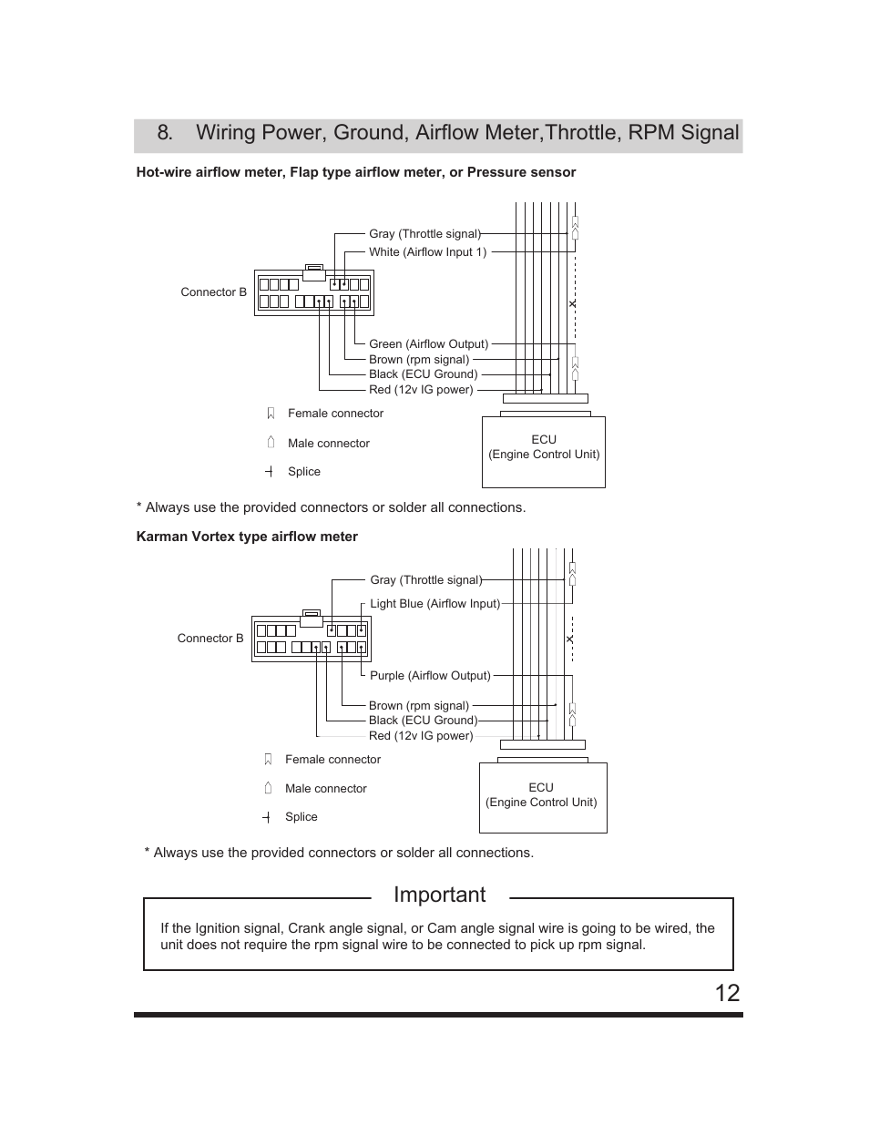
It can damage the unit as well as the vehicles electrical system.Įmanage blue wiring diagram best welding install a greddy in evolution 8 toyota unser schematic e manage ultimate operation manual g reddy injector ground wire goes info s2ki honda s2000 software untitled Emanage Blue Wiring Diagram Best Fusebox And Wave Le Contentflowservice It Emanage Blue Wiring Diagram Welding Cart Bobcate S70 Tukune Jeanjaures37 Fr.

This site is organized alphabetically by author.

Ground yourself to a light switch screw or something. The complete installation guide for a turbo conversion including E-manage Blue wiring diagrams for the 1ZZ is available HERE 1. OK Now you have all of the main wiring done double check all of your connections reconnect the wiring harness to your ECU.
#YARIS GREDDY EMANAGE BLUE WIRING DIAGRAM FREE#
Https Encrypted Tbn0 Gstatic Com Images Q Tbn And9gcr9ygij Sgd3m3arrwcqodihfoac6siu2myjtwfdmjsks3 Vsu Usqp Cau Most of the books here are free but there are some downloads that require a small fee.Įmanage blue wiring diagram. Union blocks are shaded to clearly separate Elsewhere.5 Pure Performance UK 5.
#YARIS GREDDY EMANAGE BLUE WIRING DIAGRAM CODE#
: union block (the number in the circle is the J / B) Housing no and connector code is displayed next to it). The code is the same as the code used in the parts position. : represents a part (all parts are shown in blue sky).
#YARIS GREDDY EMANAGE BLUE WIRING DIAGRAM SERIAL NUMBER#
The third character indicates a serial number used To distinguish between wiring harness Combinations in cases in which more than one of The same combination of wire harnesses, exists (For example, CH 1 and CH 2). The first character of the code of the connector indicates The alphabetic code assigned to harness Having the female connector, and the second Shows that of the wiring harness that the male has Connector. : code for the (masculine and feminine) Connectors that are used to join two wires Harness connector code consists of two Alphabetic and one numeric character. : () is used to indicate a different wiring and When the model of the vehicle, the engine Type or specification is different. Unused shader and Displays only the number of relay block to distinguish it From the J / B. : title of the system : indicates a relay block. Internal wiring for each block of the union is also provided for a better understanding of Connection within a block of the union. Use the location of the relay and the routing of electrical wiring Sections to find each part, union block connectors and wiring, wiring Harness and wiring harness connectors and each circuit of the system ground points. When the operation of the circuit is understood, begin to solve the problem Circuit to isolate the cause. See the diagram of the system to understand the circuit operation. To solve any problem, first understand the operation of the circuit Where the problem was detected (see section circuit system), power supply Supplying power to that circuit (see section power source) and land points (See the section ground point). (All circuit diagrams are shown with the switches in the OFF position). Each system circuit wiring real is shown from the point where it is received power from the battery to the point of land.

This 2007 YARIS ELECTRICAL WIRING DIAGRAM manual provides information about electrical circuits installed in vehicles in a circuit for each system.


 0 kommentar(er)
